

Placement, grounding, signal checks, and maintenance practices for flame rectification systems.
FLAME RECTIFICATION REFERENCE
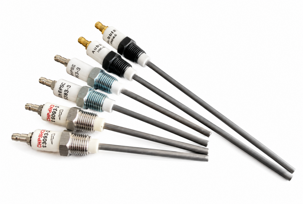
The flame rod only works when the flame completes the circuit.
Reliable flame proof depends on strong ionization, solid ground contact, correct rod placement, clean insulation, and a stable signal back to the flame safeguard.
1. Relay signal
The flame relay sends a low-current signal to the flame rod.
2. Ionized flame
The flame conducts from the rod to the grounded burner.
3. Rectification
A larger ground area lets the flame produce a DC flame signal.
4. Proof
The safeguard confirms flame only when the signal is stable.
4:1
minimum flame-ground area to flame rod area
<500 deg F
ceramic insulator temperature limit
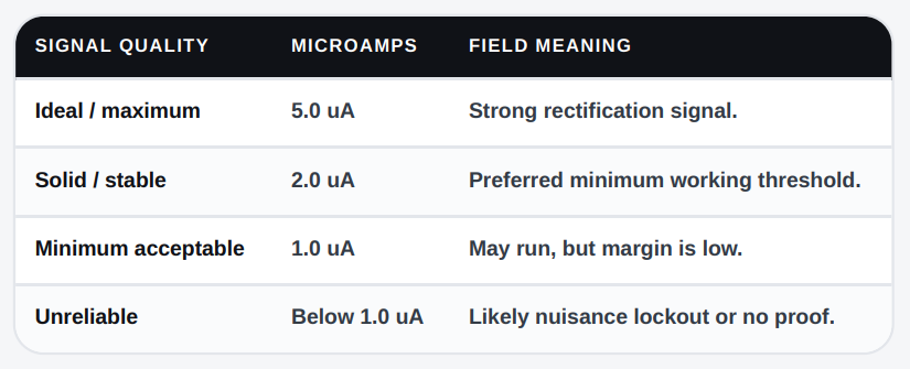
5.0 uA
ideal flame signal target where applicable
2.0 uA
stable signal threshold; below this is trouble
150ft
recommended maximum signal-lead distance
PLACEMENT MAP
Good geometry is the difference between a strong flame signal and repeat nuisance lockouts.
01 / PILOT CHOICE
Use a compatible pilot.
Pre-mixed pilots are preferred because they produce high ionization and strong flame-to-ground contact. The pilot must stay stable through draft and turndown.
02 / AIR-GAS RATIO
Keep combustion on ratio.
The proper air-gas ratio gives maximum flame temperature and stronger flame ionization. Do not troubleshoot the rod before checking the flame.
01 / PILOT CHOICE
Put only the tip in the flame.
Cut or position the rod so the tip is in the forward flame discharge. Excess rod in the flame weakens the 4:1 grounding ratio.
04 / INTERSECTION
Aim for pilot and main flame overlap.
When possible, locate the tip where pilot flame and main flame intersect, and confirm contact at every firing condition.
05 / ORIENTATION
Do not let a lazy flame fool the system.
Place the rod below the flame, beside the flame, or vertically above it so it does not prove a weak pilot that cannot light the main flame.
06 / GROUND AREA
Add ground surface when needed.
If the burner ground area is too small, add grounding vanes, pins, or rods so
the flame has a solid earth-ground path.
HEAT + MATERIAL LIMITS
A
Protect the ceramic insulator.
Keep the insulator below 500 deg F. Above that point it can become conductive and shunt signal away from the rod.
B
Select the right rod material.
Standard stainless rods are generally used up to 2400 deg F; special ceramic rods can be used up to 2600 deg F.
C
Watch for sagging or deformation.
If the rod droops out of the flame envelope, upgrade the rod type or replace the assembly.
D
Do not ignore radiant heat.
Shield or relocate the assembly when the insulator is being overheated by the burner block or refractory.
SIGNAL TARGETS
Use the OEM test method for the installed flame safeguard. Record flame signal after setup, after cleaning, and after repairs.
FAULT FINDER
USE WHEN FLAME FAILS TO PROVE
Flame is lifting.
The flame must physically touch both the burner ground and the flame rod. High pressure can lift the flame off the nozzle and break the circuit.
Action: seat the flame back on the nozzle and verify pressure.
Rod or ceramic is dirty.
Carbon, soot, and scale become conductive at high temperature and can shunt signal away from the flame safeguard.
Action: clean with fine sandpaper or emery cloth.
Ignition is interfering.
High-voltage ignition can flash over to the flame rod, causing false flame sensing or amplifier damage.
Action: separate electrode and rod or add a grounding vane.
Ground path is weak.
Small ground area, hot refractory, loose bonding, or cabinet grounding problems can reduce or interrupt the flame signal.
Action: verify continuity and add grounding area.
TECHNICIAN CHECKOUT
A fast field list for annual service, startup, and troubleshooting documentation.
Verify rod tip location.
Forward discharge; pilot/main intersection where possible.
Clean rod and insulator.
Remove carbon, soot, scale, and tracking marks.
Check insulator temperature.
Keep ceramic below 500 deg F
Separate from ignition.
Prevent flashover and false flame proving.
Confirm 4:1 ground ratio.
Add vanes, pins, or rods when ground area is low.
Measure flame signal.
Record uA or display voltage per the safeguard manual.
Inspect wiring route.
Use #14 signal wiring where required and keep length under 150 ft
Verify burner ground continuity.
Burner, panel, and earth ground must share a solid path.
Office: 870-735-7555
Field reference only. Always verify final installation, signal testing, replacement parts, and safety procedures against the current equipment manual, flame safeguard instructions, adopted code requirements, and site policies